9.1.09

Nokia 5510, N-Gage, N800 Internet, N95, N91, N76, 7390, 6300, 6290, 6267, 5700 Xpress, 5300 Xpress, 5200 DKE-2 mini-USB cable scheme pinout


Nokia 5510, N-Gage, N800 Internet, N95, N91, N76, 7390, 6300, 6290, 6267, 5700 Xpress, 5300 Xpress, 5200 DKE-2 mini-USB cable scheme pinout


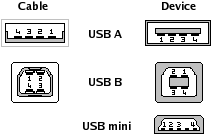
Đây là tiêu chuẩn giao diện mini-usb .

Pin Name Description
1VCC+5 VDC
2D-Data -
3D+Data +
x
Bỏ trống hoặc nối đất GND (có thể qua điện trở).
4GNDĐất

Màu dây:

Pin Name Cable color Description
1VCCRed+5 VDC
2D-WhiteData -
3D+GreenData +
4GNDBlackGround

Nokia Pop-port pinout


This external connector for Nokia 2112, 2115(i), 2116i, 2125i, 2126i, 2128i, 2270, 2272, 2280, 2285, 3100, 3105, 3108, 3120, 3125, 3200, 3205, 3220, 3300, 3570, 3580, 3585(i), 3586(i), 3587(i), 3588i, 3589i, 3220, 5100, 5140, 6011i, 6012, 6015(i), 6016i, 6019i, 6020, 6100, 6101, 6102, 6108, 6200, 6220, 6225, 6560, 6585(i), 6610, 6610i, 6800, 6810, 6820, 6822, 6200, 7200, 7210, 7250, 7250i, 7260, 7360, 7610, 9300, E50, E60, E61, E61i, E65, E70, N70, N71, N72, N73, N80, N90, N92, N93, N93i.....

The port contains signals for handsfree microphone, stereo speakers, FBus Rx/Tx or USB signals for the phones supporting them, power output for feeding the accessories that don"t have their own batteries, and the Accessory Control Interface (ACI), a bidirectional serial control bus for connection of phone accessories, with a proprietary protocol.

Pin
Number
Pin
Name
Description
1 Vin Charger input
2 GND Charger ground
3 ACI Accessory Control Interface (short with pin 2 for handsfree recognition)
4 V Out Connected to pin 3 in DKU-2 usb data cable
5 USB Vbus Also act as USB power detection? Should be connected to USB pin 1 in usb data cable.
6 FBus Rx/USB D+ USB exists only in some models*. Should be connected to USB pin 3 in usb data cable.
7 FBus Tx/USB D- USB exists only in some models*. Should be connected to USB pin 2 in usb data cable.
8 GND Data GND
9 X Mic- Audio in - Ext. Mic input negativ
10 X Mic+ Audio in - Ext. Mic input positiv
11 HS Ear L- Audio out - Ext. Audio out - left, negativ
12 HS Ear L+ Audio out - Ext. Audio out - left, positiv
13 HS Ear R- Audio out - Ext. audio out - right, negativ
14 HS Ear R+ Audio out - Ext. audio out - right, positiv. Pins 10-14 may be used for antenna connection.

GND shield GND in cavities
* Nokia N70, N90, N91, 3230, 3300, 6155, 6170, 6230, 6230i, 6235, 6255, 6260, 6630, 6650, 6670, 6680, 6681, 7270, 7600, 7610, 7700, 7710, 9300, 9500 and some others. You may connect these phones to computer USB port by simple straight-wired USB cable (see DKU-2 schematic above).

Nokia smartphone headset handsfree pinout


Nokia Smartphone 2.5 mm headset connector

Pin
Name
Pin
Number
Description
1 Left Audio Left
2 Right Audio Right
3 Mic Mic
4 Ground Ground

Nokia Smartphone headset handsfree pinouts

Pin 3 used for both Mic and C-video (multiplexed) in Nokia N95

Nokia headset / handsfree HDB-5 connector and schematics pinout


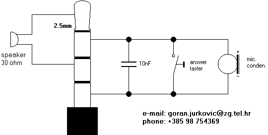
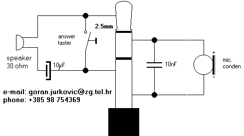
Wiring for the nokia 2.5mm 4-pole headset socket of Nokia 1100, 1101, 1110, 1600, 2100, 2300, 2500, 2650, 2652, 3210, 3310, 3330, 3410, 3510, 3510i, 3650, 3660, 5210, 6030, 6060, 6120, 6510, 6600, 7280, 7380 7650, 8210, 8310, 8800, 8850, 8890, 8910, 8910i cell phones (except some smartphones)


Pin
Name Direction Description
1 Tip Speaker +
2 Ring 1 Microphone +
3 Ring 2 Speaker -
4 Sleeve Microphone -
The answer/end button should be connected across the microphone connections.


Nokia 3210 handsfree / headset schematic

Nokia headset schematic

Nokia 8210 handsfree / headset schematic

Nokia handsfree schematic

Nokia n95, n95-8gb, n82 tv out cable pinout


4 pin (3.5mm jack) to 3 pin rca (audio,video )

4 pin jack

r c a rca colour
1 audio left white
2 audio right red
3 video yellow
4 signal mix

Memory stick (MS) card pinout


Memory Stick is a removable flash memory card format, used mostly in Sony portable hardware.

Variations includes the Memory Stick Pro, a revision that allows greater maximum storage capacity and faster file transfer speeds; Memory Stick Duo, a small-form-factor version of the Memory Stick (including the Pro Duo); and the even smaller Memory Stick Micro (M2). The Memory Stick is defined in the minds of many by its proprietary nature, as the majority of portable devices that use it are Sony and Sony Ericsson devices.

Memory stick is read or written by half-duplex serial protocol of three-wire system. Write speed is 1,800MB - 330KB/s. Depends on flash memory cell. Read speed is 2.45MB/s.

PinPin
Name
Description
1 VSS Vss
2 BS Bus state signal
3 DATA1 Data1 Parallel / NC Serial
4 SDIO/DATA0 Data0 Parallel / Data Serial
5 DATA2 Data2 Parallel / NC Serial
6 INS Stick detect (connected to VSS)
7 DATA3 Data3 Parallel / NC Serial
8 SCLK Clock signal
9 VCC Vcc (2,7V - 3,6V)
10 VSS Vss

MultiMedia Card (MMC) pinout


MMC memory cards are up to 1Gb and uses up to 20MHz 1-bit data bus

The MultiMedia Card communication is based on serial bus designed to operate in a low voltage range.

PinSignalDescription
1RSV NCNot connected or Always ?1? (data 3?)
2CMD I/OCommand/Response
3VSS1 SSupply Voltage Ground
4VDD SSupply Voltage
5CLK IClock
6VSS2 SSupply Voltage Ground
7DAT0 I/OPP Data 0
  • CLK - with each cycle of this signal an one bit transfer on the command and data lines is done. The frequency may vary between 0-20MHz.
  • CMD - is a bidirectional command channel used for card initialization and data transfer commands.
  • DAT - is a bidirectional data channel. The DAT signal operates in push-pull mode. Only one card or the host is driving this signal at a time.

For compatibility to existing controllers the cards may offer,in addition to the MultiMedia Card mode, an alternate general-purpose synchronous serial interface which is based on the SPI (Serial Peripheral Interface) standard.

PinSignalDescription
1CS Chip select (neg. true)
2DI DATA in
3Vss Ground
4Vcc Power supply
5SCLK Clock
6Vss2 Ground
7DO DATA out

The MultiMediaCard card identification and addressing methods are replaced by a hardware Chip Select (CS) signal. For every command, a card (slave) is selected by asserting the CS signal (active low). The CS signal must be continuously active for the duration of the SPI transactions. The MM card bidirectional CMD and DAT lines are replaced by unidirectional DATA in and DATA out signals (single and multiple block read/write commands are supported).

Secure Digital (SD) card pinout


Secure Digital (SD) is a flash memory memory card format used in portable devices, including digital cameras and handheld computers.

SD cards are based on the older Multi Media Card (MMC) format, but most are physically slightly thicker than MMC cards. They also boast higher data transfer rates. DRM features are available but are little-used. SD cards generally measure 32 mm × 24 mm × 2.1 mm, but can be as thin as 1.4 mm, just like MMC cards.

There are different speed grades available. They are referred to with the same nx notation as CD-ROMs; a multiple of 150 kB/s. Devices with SD slots can use the thinner MMC cards, but the standard SD cards will not fit into the thinner MMC slots. MiniSD and MicroSD cards can be used directly in SD slots with an adapter. There are readers which allow SD cards to be accessed via many connectivity ports such as USB, FireWire.

Pin SD Mode SPI Mode
Name Type Description Name Type Description
1 CD/DAT3 I/O/PP Card detection / Connector data line 3 CS I Chip selection in low status
2 CMD PP Command/Response line DI I Data input
3 Vss1 S Supply voltage (earth) VSS S Supply voltage
4 Vdd S Power supply VDD S Power supply
5 CLK I Clock SCLK I Clock
6 Vss2 S Supply voltage VSS2 S Supply voltage
7 DAT0 I/O/PP Connector data line 0 DO O/PP Data output
8 DAT1 I/O/PP Connector data line 1 RSV
9 DAT2 I/O/PP Connector data line 2 RSV

SD card"s interface is compatible with standard MMC card operations. All SD memory and SDIO cards are required to support the older SPI/MMC mode which supports the slightly slower four-wire serial interface (clock, serial in, serial out, chip select) that is compatible with SPI ports on many microcontrollers. Many digital cameras, digital audio players, and other portable devices probably use MMC mode exclusively. MMC mode does not provide access to the proprietary encryption features of SD cards, and the free SD documentation does not describe these features. As the SD encryption exists primarily for media producers, it is not of much use to consumers who typically use SD cards to hold unprotected data.

There are three transfer modes supported by SD: SPI mode (separate serial in and serial out), one-bit SD mode (separate command and data channels and a proprietary transfer format), and four-bit SD mode (uses extra pins plus some reassigned pins) to support four bit wide parallel transfers. Low speed cards support 0 to 400 kbit/s data rate and SPI and one-bit SD transfer modes. High speed cards support 0 to 100 Mbit/s data rate in four-bit mode and 0?25 Mbit/s in SPI and one-bit SD modes.

SD cards security features includes:

  • Copyright protection mechanism with the SDMI standard (Secure Digital Music Initiative)
  • Integrated CPRM file protection and encryption system (CPRM is a Content Protection for Recordable Media)

headphone pinout


O2 Xda, Qtek 1010, 1020, Siemens SX56, T-Mobile MDA, Dopod 686 (all Wallaby)


Wallaby (O2 Xda, Qtek 1010, 1020, Siemens SX56, T-Mobile MDA, Dopod 686) headphones:

Pin Signal Description
1 (Tip)Left ear White
2 (Ring 1)Right ear Red
3 (Ring 2)Mic/switch Blue. Short this pin to GND to pick up the phone
4 (Sleeve)Ground Copper


Headphones for Blue Angel (O2 Xda IIs, O2 Xda III, Dopod 700, I-mate PDA2k, T-Mobile MDA III, Orange SPV M2000, Qtek 9090, Siemens SX66.

Pin Signal Description
3 (Ring 2)Left ear
2 (Ring 1)Right ear
4 (Sleeve)Ground

PDA cable connector pinout


O2 Xda, Qtek 1010, 1020, Siemens SX56, T-Mobile MDA, Dopod 686 (all Wallaby); O2 Xda II, Qtek 2020, SPV M1000, Dopod 696 (all Himalaya); Audiovox PPC-6600, PPC-6601, VX6600; PDA cable connector pinout


Wallaby and Himalaya come with two connectors on the bottom. Also for MDA, XDA, Eurotel DataPhone.

This full pinout suggested for Wallaby, Himalaya, T-mobile O2 XDA, HTC Pocket PC phones. For other devices it may be little different (only USB signals are confirmed to be the same for all devices listed at the top of this page).

PinSignalDescription
1CAR_MIC_INCar microphone input
2GND / SENSEGround / chassis
3CAR_AUDIO_RCar audio right output
4CAR_AUDIO_LCar audio left output
5ANALOG GND
6RS232_DCD
7RS232_CTS
8RS232_TXD
9RS232_RTS
10RS232_RXD
11RS232_DTR
12NC
13USB_VDDUSB voltage detection
14UDC+USB data positive voltage
15UDC-USB data ground/negative
16,17,18GND
19CAR_ON#
20,21,22V_ADP+5 volts DC to charge/power the unit

Notes:
Some users report that serial interface is TTL logic which needs to be inverted (required) and voltages shifted ( not necessarily required) to be recognized by an RS232 interface.

CAR_ON# is connected to +6V/+5V on the car charger, it"s not connected in the cradle. +6V/+5V makes the phone go to speaker mode immediately when picked up or dialing. When this pin is connected to ground, the internal mike and speaker are turned off, and audio input is taken from the audio input pin on the connector, for use in real car kits.
Pin 2 GND / SENSE is not necessary. it seems that if it"s grounded, the phone hangs up when placed in a DIY Car-holder for example. - leave it unconnected.
Pin 5 ANALOG GND - connect this to your sound Input/output-GND (Speaker/Microphone) - do not connect this with the other GND"s - it makes a lot of noise on the analog input/outputs. Audio needs to be capacitively coupled in, any DC bias seems to inhibit audio.

If RS232_DCD is pulled to +6V/+5V, the device turns on and ActiveSync is started. The serial port powers down and needs to be reopened after the device goes in power-save mode.

USB power also wakes up the device and starts ActiveSync. UDC+ and UDC- are the USB data connections. One person reported measuring them the other way around.

Cable to plug into computer

This is the cable you need to talk to the Wallaby or Himalaya serially from a computer, such as is needed with our Manipulator program or for using ActiveSync through the serial port. Techies like us call it a "null-modem cable", O2 describes it as a "serial hotsync cable". Optionally, if you wish to be able to power/charge to XDA while using this cable, you could hook up a female connector that mates with the connector on your power adapter between Ground (pins 2,5,etc. on XDA) and pins 20,21 and 22 on the XDA. Make sure the center conductor on the power connector goes to pins 20,21 and 22.

Wallaby /
Himalaya
9-pin connector
(male)
2,5,16,17,185 (gnd)
6 (dcd)4 (dtr)
7 (cts)7 (rts)
8 (txd)2 (rxd)
9 (rts)8 (cts)
10 (rxd)3 (txd)
11 (dtr)6,1 (dsr, dcd)

Cable to plug into modem or GPS

This cable will connect to devices which come with a cable to plug into a PC serial port, such as a modem. If you are connecting to a device that only uses RX, TX and GND (such as many GPS receivers), you may only need the wires which connect to pins 2, 3 and 5 on the 9-pin serial connector. And you can, optionally, hook up a charging interface in the same way as described above.

Wallaby /
Himalaya
9-pin connector
(female)
2,5,16,17,185 (gnd)
6 (dcd)1 (dcd)
7 (cts)8 (cts)
8 (txd)3 (txd)
9 (rts)7 (rts)
10 (rxd)2 (rxd)
11 (dtr)4 (dtr)

Modifying iPaq accessories

Using the pinout of the XDA connector, you can now modify iPaq accessories to fit the Wallaby or Himalaya.

Wallaby /
Himalaya
iPaq
36xx or 37xx
iPaq
38xx or newer
2,5,16,17,18 (gnd)4,1010,15,22
6 (dcd)96
(or 11, see below)
7 (cts)513
8 (txd)78
9 (rts)612
10 (rxd)87
11 (dtr)39
14 (udc+)1119
15 (udc-)1221
20,21,22 (power)1,21,2,3,4

Apple iPhone headphone jack adapter pinout


iPhone headphone jack adapter

Số chân Tên gọi Chú thích
1 Tip Left audio
2 Ring Right audio
3 Ring Common/Ground
4 Sleeve Microphone

Tai nghe USB

6.1.09

USB pinout

Pin Signal Color Description
1 VCC
+5V
2 D-
Data -
3 D+
Data +
4 GND
Ground